Normal contact force in DEM
Introduction
In fluid simulations using computation fluid dynamics (CFD), there are many benchmark problems available for the varification of your CFD code. However, it is not quite the case for the modeling of granular materials using the discrete element method (DEM). I think the major reason is the explicit description of particles in DEM simulations. In most cases, people pay less attention to the specific behavior of an individual particle. Instead, the collective behavior of a group of particles is more important. As a result, it is less meaningful to replicate the exact particle positions and sizes, which are commonly automatically generated using a certain random number. In fact, it is a common practice to repeat the DEM simulation of the same problem with different random numbers to make sure that the numerical results are statistically consistent.
Therefore, it seems that the easy verification of your DEM code is possible only when the problem involves a few particles and their kinematics can be easily predicted even by intuition. Here, we are going to verify the normal force calculations in our own 2D DEM code by considering a particle moving towards another fixed particle.
Model
Let \(\boldsymbol{x}_1\) and \(\boldsymbol{x}_2\) be the centers of particles of radii \(r_1\) and \(r_2\), respectively. Then, the relative position \(\boldsymbol{x}_{12}\) from particle 1 to particle 2 is
\[\boldsymbol{x}_{12} = \boldsymbol{x}_2 - \boldsymbol{x}_1.\]The overlap between particle 1 and particle 2 can be calculated as
\[\delta = r_1 + r_2 - |\boldsymbol{x}_{12}|.\]A nonzero contact force exists only when \(\delta > 0\). The unit normal vector is
\[\boldsymbol{n} = \frac{\boldsymbol{x}_{12}}{|\boldsymbol{x}_{12}|}.\]Now, we have defined all the geometric parameters necessary for the normal contact force calculations. To consider the energy loss due to particle collisions, the inter-particle contact force is composed of an elastic part, which is a function of the overlap \(\delta\), and an inelastic part, which depends on the relative velocity. First, let us calculate the elastic part using a linear spring model
\[\boldsymbol{F}_1 = (k_n \delta) \boldsymbol{n},\]where \(k_n\) is the normal stiffness of the spring (material). To calculate the inelastic part of the normal contact force, a dashpot model is adopted
\[\boldsymbol{F}_2 = c_n (\boldsymbol{u}_{12} \cdot \boldsymbol{n}) \boldsymbol{n},\]where \(c_n\) is the damping coefficient and \(\boldsymbol{u}_{12}\) is the relative velocity from particle 1 to particle 2, i.e.
\[\boldsymbol{u}_{12} = \boldsymbol{u}_2 - \boldsymbol{u}_1.\]The translational velocities of particle 1 and particle 2 are denoted by \(\boldsymbol{u}_1\) and \(\boldsymbol{u}_2\), respectively. Given a coefficient of normal restitution \(\varepsilon\), the damping coefficient \(c_n\) can be calculated as
\[c_n = \frac{2 \sqrt{k_n m_{eff}}}{\sqrt{1+(\pi / \ln{\varepsilon})^2}},\]where \(m_{eff}\) is the reduced mass. Let \(m_1\) and \(m_2\) be the masses of particles 1 and 2, respectively, we have
\[m_{eff} = \frac{m_1 m_2}{m_1 + m_2}.\]Finallly, the total normal contact force acting on particle 1 is
\[\boldsymbol{F}_n = -\boldsymbol{F}_1 + \boldsymbol{F}_2.\]An equal and opposite normal contact force (\(-\boldsymbol{F}_n\)) is applied to particle 2.
Verification
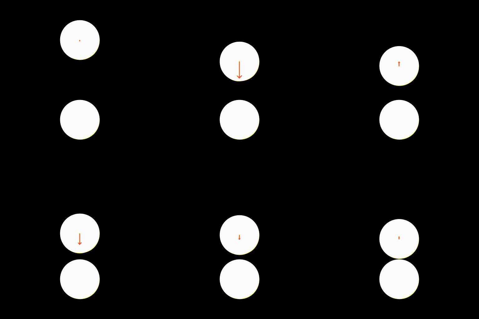
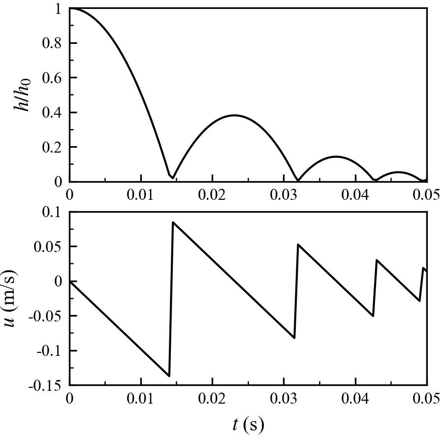
The case of a particle falling onto another fixed particle is considered to verify the DEM code. Since my education background is geotechnical engineering, I would like to assign properties of sand to the interactiing particles. Here, the simulation involves two particles of the same size with their diameters \(d_p = 1 \ \mathrm{mm}\). The particle density is \(\rho_p = 2500 \ \mathrm{kg/m^3}\). The particle normal stiffness is \(k_n = 10^9 \ \mathrm{N/m}\). The restitution coefficient is \(\varepsilon = 0.5\). The lower particle is fixed at the location \((0, 0)\). The upper particle is initially placed at \((0, 2d_p)\), which is released at \(t = 0 \ \mathrm{s}\) and falls under the gravity \(g = 9.81 \ \mathrm{m/s^2}\). The time step is set to be a small value to fully resolve the collision process \(\Delta t = 5 \times 10^{-8} \ \mathrm{s}\). The whole simulation lasts for \(0.05 \ \mathrm{s}\). During the simulation, we record the height \(h\) and the falling velocity \(u\) of the upper particle.


We can see that the upper particle falls down and bounces back. This process repeats as time goes by. But for each cycle, the particle always cannot recover its original height due to the energy loss during impact. Here, it is noted that the actual coefficient of restitution seems to be smaller than the value we specified, i.e., \(0.5\).
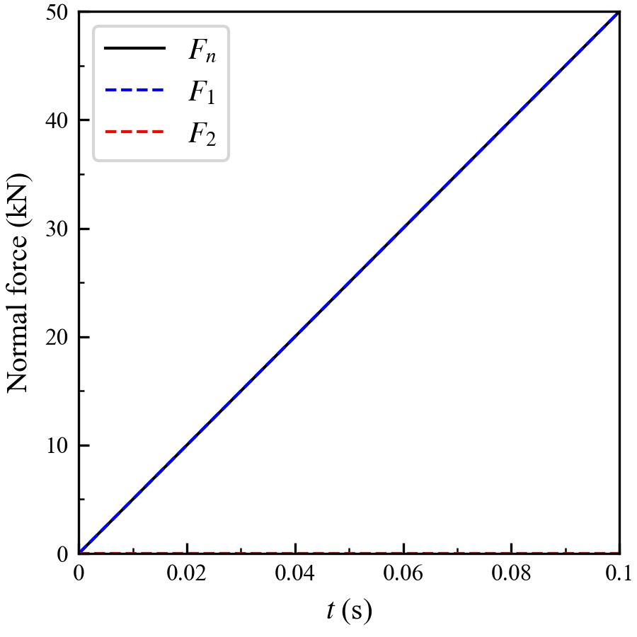
In the falling particle scenario, we can easily see whether the particle kinematics makes sense or not, but it is relatively difficult to judge the accuracy of the normal force calculation due to the short contact period. Therefore, we study another similar case by moving the upper particle towards the lower fixed particle with a small constant velocity (\(0.001 \ \mathrm{m/s}\)). Initially, the two particles are just in contact, so we should be able to record a nonzero contact force once the simulation starts.


We can see that the normal contact force increases gradually as the upper particle moves closer and closer to the lower fixed particle. Due to the large stiffness and the small velocity, the inelastic part of the normal contact force \(F_2\) turns out to be much smaller than the elastic part \(F_1\). As a result, the total normal contact force \(F_n\) is almost the same as the elastic component \(F_1\), and they increase linearly during the whole simulation. We can do a simple calculation to check the force magnitude. After \(0.1 \ \mathrm{s}\), the overlap should be \(10^{-4} \ \mathrm{m}\). Since the stiffness of each grain is \(10^9 \ \mathrm{N/m}\), the effective contact stiffness is halved, and the resulting normal contact force should be \(5 \times 10^4 \ \mathrm{N}\) or \(50 \ \mathrm{kN}\). The numerial result agrees with the theoretical solution.
Summary
We have verified the normal contact force calculation in DEM simulations by considering two simple scenarios. We find
-
The direction of the normal contact force is correctly imposed. The elastic component generates a repulsive force and the inelastic component is against the relative motion.
-
The magnitude of the normal contact force is correctly imposed. With a constant relative velocity and a certain contact overlap, the numerical result agrees with the value calculated by hand.
Enjoy Reading This Article?
Here are some more articles you might like to read next: